Buchla & M.E.M.S. Programmable Spectral Processor Model 296
$449.00
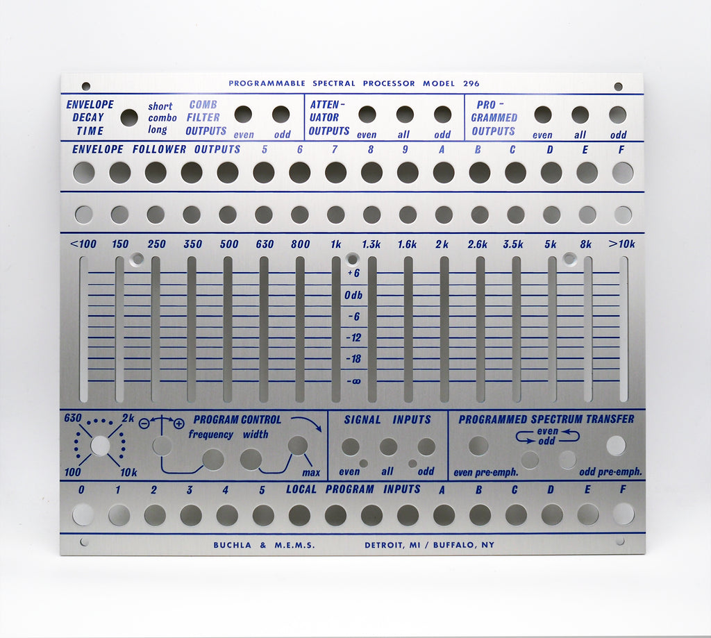
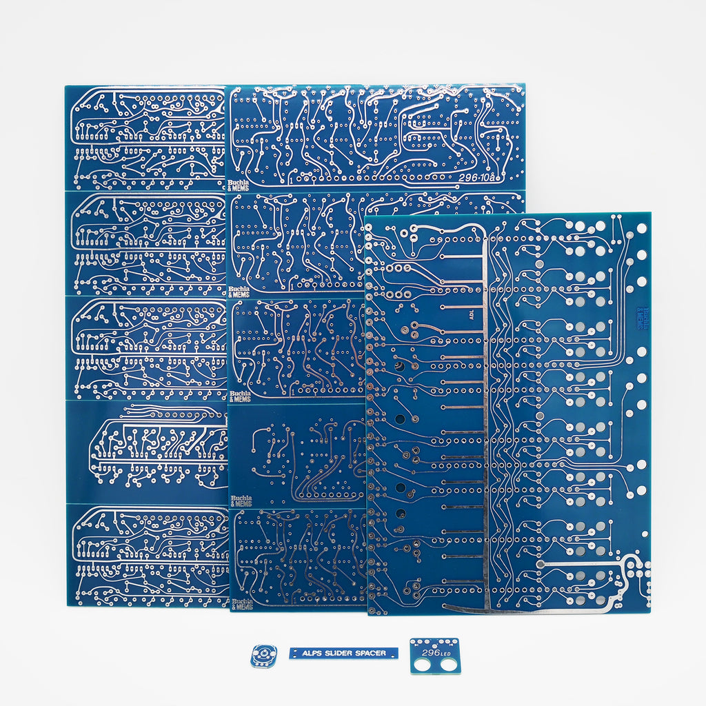
A set of 11 Main PCBs + 25 "accessory" PCBs + 1 front panel. V2164M adapters are not shown in the photo but eight are included.
Additional Part recommendation: quantity 5x M.E.M.S. 9mm to PRV6 Adapter
The PROGRAMMABLE SPECTRAL PROCESSOR MODEL 296 is an elaborate set of filters with a number of different outputs and special functions. Perhaps its most obvious function is that of a sixteen band graphic equalizer. The sixteen bands are labeled in hex (0 through F) at the top and bottom of the module and the center frequency of each band is indicated above each slider attenuator.
- ATTENUATOR OUTPUTS
The signal input jacks, in the center beneath the sliders, offer the choice of putting a signal in to the eight even numbered bands, all sixteen bands, or the eight odd bands. (Note that these are just the even or odd numbered bands on the equalizer and have no correspondence to even or odd harmonics.) The ATTENUATOR OUTPUTS at the top of the module also offer "even", "odd", or "all" signal outputs. With a signal patched into the "ALL" signal input and taken out through the "All" attenuator output the module functions just as a sixteen band graphic equalizer. Note on the scale for the attenuators that 0 dB is just below the top range of the sliders and that a slider at the very top is actually giving a 6 dB boost to frequencies in that band. An attenuator at the very bottom will completely cut off any signal in that frequency band. The signal output jacks directly above each attenuator offer the signal present within that frequency band. These outputs are not affected by the attenuator's positions. The COMB FILTER outputs offer the
signals from either all the "even" or all of the "odd" bands and are also unaffected by the attenuators. - CONTROL VOLTAGE OUTPUTS
The control voltage outputs labeled ENVELOPE OUTPUTS are envelope follower outputs for each frequency band. In other words, the voltage from these outputs represents the amplitude of the signal present within each band. The switch in the upper left-hand corner selects "long" or "short" envelope decay times. These outputs are not affected by the positions of the attenuators. - PROGRAMMED OUTPUTS
The SPECTRAL PROCESSOR can be voltage controlled in a variety of ways. The results of any control voltage manipulation are presented to the PROGRAMMED signal outputs. It is possible to "sweep" through the various frequency bands much (much like a bandpass filter can "sweep" the frequency spectrum) using the pot on the far left· of the PROGRAM CONTROL section. This pot can be voltage controlled through the control voltage input labeled FREQ. The small knob beside the input is an inverting attenuator the same as others on the synthesizer. On the right is a WIDTH control pot which determines the widths of the sixteen frequency bands. The labeling above each attenuator indicates the
approximate center frequency of each band. Notice that as the bandwidth gets very narrow "gaps" appear: between each band and then the bands disappear completely and no signal is passed. At The MAX setting each band is so wide as to encompass the entire frequency spectrum and the FREQ control will have no effect. This pot can be voltage controlled but it has no attenuator on the control voltage. The LOCAL PROGRAM INPUTS allow individual voltage control of the signal level in each frequency band. With no control voltage the signal for that band is cut off. As a control voltage increases the signal is gradually unattenuated. - SPECTRAL BIAS
The pair of knobs and switches labeled SPECTRAL BIAS have a function often associated with a "vocoder" circuit. Unfortunately the labeling on these controls has no relationship to their function and should be ignored. (They were originally intended for a different purpose). The left switch, when up, patches each "even" envelope follower output into its neighboring "odd" control voltage input. In effect this causes the SPECTRAL PROCESSOR to analyze the signal present at the "even" input and to duplicate its frequency spectrum in the "odd" bands. If the signal presented to the "odd" input has a broad enough frequency spectrum itself the "odd" PROGRAMMED OUTPUTS will match timbres with the "even" signal. The right switch performs the same function going from "odd" to "even". (NOTE: Despite the fact that this is a three position switch, only the top and bottom positions have any function.) If a microphone signal is the signal being analyzed, a harmonically rich signal from an oscillator can be made to duplicate vowel sounds in speech. (This is known as a "vocoder" patch.) For this to work best the input signal requires special equalization. This is the purpose of the two knobs. When turned to the right they boost the treble range of the "even" and "odd" input signals respectively. Since they affect both the ATTENUATOR and PROGRAMMED outputs they should be turned down (to the left) unless setting up a "vocoder" patch. Be aware that the BANDWIDTH and FREQUENCY controls are still in effect when using these switches. For best results in a "vocoder" patch, BANDWIDTH should be set fairly narrow and FREQUENCY set to about the same range as the output signal.